CPUID instruction: see Intel Architecture Software Developer's Manual, Volume 2, P3-114.
Control Registers: The five control registers (CR0 through CR5) determine the operating mode of the processor and the characteristics of the currently executing task (see the section titled "Control Registers" in Chapter 2 of the Intel Architecture Software Developer's Manual, Volume 3).
GDTR, LDTR: see Chapter 7 of "Protected Mode Software Architecture". They are used in protected mode for segment management.

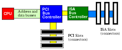
Connection of the PCI and ISA Busses in a Typical PC

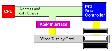
AGP Bus Interface
See http://webster.cs.ucr.edu/Page_AoAWin/HTML/IOa2.html
totally there are 216 I/O ports.
There are 4 classes of ports:
Read-only port: A read-only port is (obviously) an input port. If the CPU can only read the data from the port, then that port is providing data appearing on lines external to the CPU. The system typically ignores any attempt to write data to a read-only port.
Write-only port: A write-only port is always an output port. Writing data to such a port presents the data for use by an external device. Attempting to read data from a write-only port generally returns garbage.
Read-Write Port: A read/write port is an output port as far as the outside world is concerned. However, the CPU can read as well as write data to such a port. Whenever the CPU reads data from a read/write port, it reads the data that was last written to the port.
Dual Port: A dual I/O port is also a read/write port, but reading the port reads data from some external device while writing data to the port transmits data to a different external device.
Ports allocation:
Port 00-FF are reserved for the system motherboard (not available for adapter card). Most systems ignore address lines A1 through A4 for I/O addresses 20h-3Fh. Therefore, you can only see two ports between 20h - 3Fh, which are 1****0 and 1****1 (20h and 21h).
Many motherboards include adapter cards built onto the motherboard. All these built-in adapters use ports in the range 100h to 3ffh.
See undocumented PC page 800 and Ralf Brown's Interrupt List.
There are three basic forms of input and output that a typical computer system will use: I/O-mapped I/O, memory-mapped I/O, and direct memory access (DMA). I/O-mapped input/output uses special instructions to transfer data between the computer system and the outside world; memory-mapped I/O uses special memory locations in the normal address space of the CPU to communicate with real-world devices; DMA is a special form of memory-mapped I/O where the peripheral device reads and writes data in memory without going through the CPU.
Memory-mapped I/O: A memory mapped peripheral device is connected to the CPU's address and data lines exactly like memory. The CPU can use any instruction that accesses memory to transfer data between the CPU and a memory-mapped I/O device.
I/O-mapped I/O: I/O-mapped input/output uses special instructions (In/Out instructions) to access I/O ports.
DMA: the peripheral device accesses memory directly, without using the CPU as an intermediary. A typical DMA controller consists of a pair of counters and other circuitry that interfaces with memory and the peripheral device. One of the counters serves as an address register. This counter supplies an address on the address bus for each transfer. The second counter specifies the number of transfers to complete. Each time the peripheral device wants to transfer data to or from memory, it sends a signal to the DMA controller. The DMA controller places the value of the address counter on the address bus. At the same time, the peripheral device places data on the data bus (if this is an input operation) or reads data from the data bus (if this is an output operation). After a successful data transfer, the DMA controller increments its address register and decrements the transfer counter. This process repeats until the transfer counter decrements to zero.
Keyboard controller; Super I/O Controller; DMA Controller; Interrupt Controller; AGP Support; Plug and Play support; USB support; Cache Support; memory support; power management support...